Hanayama Nutcase Puzzle


I got this Hanayama puzzle as a late Christmas gift. Nutcase, 6 stars out of 6. It’s really tightly machined, and there are only two (kind of tricky) ways of opening it, so even if you know the solution(s), it can still be hard to take apart and reassemble (unless you practice a lot).

It is really cool, though, and it does make a challenging present if you lock a $20 bill inside before gifting it to a friend.

ROKR Mars Rover Kit


This is the third kit I got for Christmas. It had been shipped after the other two, and I didn’t get it until the beginning of January. In a way, this was a good thing because otherwise I might have started with this one, and that could have been a very confusing thing. But, after having experienced building the other two first, I was more prepared to take on the Rover. It’s got 4 sheets of pre-lasercut plywood, a few steel pins, 20 plastic spacers, a couple plastic gears, 2 wooden dowels, and a tiny sheet of sandpaper (the box photo shows 2 sheets). There’s also the solar panel and motor assembly. The instructions claimed that there was also supposed to be a tube of wood glue, but that was missing. Fortunately, I still had the tube I’d bought for the Airship. I had no need for the sandpaper, and instead used a cutter knife for smoothing out nubs on the wooden pieces, when needed.

The packaging says the finished kit is 175x85x100mm (6.9″ x 3.4″ x 3.9″). It’s small, but it’s cute. You will need a cutter knife, a cutting pad, and wood glue.

Pieces for two of the spacer stands, and for the motor drive shaft.
Again, there were 4 stands for properly aligning the various spacers on the metal pins. Unfortunately, the instructions were not very good this time. One illustration referenced the wrong space stand. Another picture was missing the part number for one of the tire pieces. And, quite a few of the pictures indicating that you’re supposed to glue stuff together didn’t actually show where the glue is to go. It’s not that hard to figure out through trial and error, but it did add to the amount of time I took to finish the kit.

Finished stands, and the gear shaft.

Pieces for the gear box.

Finished gear box, plus pieces for the chassis left panel.

Finished left panel, plus pieces for the motor holder and chassis right panel.

Finished holder and side panels. Piece for the top motor brace, plus the motor/solar panel assembly.

Finished side panels/motor assembly. Pieces for the chassis rear and bottom panels.

Finished chassis box bottom.

Pieces for the left suspension system, plus front and back wheel axels. This is the first point I really got confused as to what I was supposed to be gluing together. Turns out, the two blocks of knobby pieces get glued together to make sideways stacks of spacers. The disks are more-or-less aligned to look like one wide gear, even though the stacks don’t rotate on the axel.

Finished left suspension system.

Left suspension system mounted on the chassis bottom. Pieces for the right suspension system. Same comments as above.

Pieces for two of the wheels. These two have the square plastic inserts that fit into the hub gap. These two are mounted on the motor drive shaft, and are the ones that actually propel the rover forward when/if the panel gets enough light. The spokes do have an “alignment”, and it looks better if all the wheels are mounted to have identical alignments (spokes angled frontward or rearward).

Chassis bottom with the first two wheels mounted. Plus pieces for the other four wheels. These are just popped into the support holes in the suspension frames, and are free-turning. Again, a lot more gluing. The instructions state that the gear teeth for the three disks for each wheel be staggered from each other. I guess this is for traction.

Finished wheels mounted in the suspension frames. Plus pieces for the rear solar panel support frame.

Pieces for the front headlights, and the primary front probe arm.

Finished front chassis panel, mounted, with headlights and probe arm. The rear solar panel support frame is also mounted, and the solar panel is double-sided taped to the support frame.

I’d started making this kit at 9:30 PM, and at 12:30 AM, I figured I’d reached a good stopping point for the night.

The assembly instructions don’t name the various subassemblies, so I’ve been kind of guessing at what to call things. I’ve run out of ideas here. These are the pieces for one of the camera/instrument boxes that goes on the top chassis plate.

Finished instrument box, plus pieces for the hatch cover arm. I decided to leave the “fiber strips/flashing” on the pieces for this photo. The kit description on the Amazon page suggested an assembly time of 4 to 6 hours, and I was really hoping to zip through this one in 3 hours because I had a bit of experience already with the Treasure Box and Airship kits. But, I was spending an inordinate amount of time on removing flashing from all the pieces, and in gluing parts together, plus ensuring that they were all aligned right. Also, I was getting to the point where I had to cut pieces from the wooden dowels, and then push them through the holes in various parts. The holes were generally too small, and I had to bore them open with a Phillips head driver. Even so, there was a lot of pushing and force involved in getting the pins to go into position correctly. Fortunately, nothing shattered up to this stage.

Finished hatch cover arm and pieces for the big camera box arm.

Finished arm, and pieces for the camera box base section.

Finished camera box base, and pieces for the box itself.

Rover top plate instrument components so far.

Finished camera box, and pieces for instrument section 2.
This is where I finally shattered something. I’d been boring out the holes in the places where the pins go before inserting them, and up to this point that had worked ok. But now, the smaller pieces were less forgiving of pressure like that, and I wasn’t able to bore as much. I had to apply a massive amount of force on the two pins on the upper arms of the camera assembly, while constantly struggling to keep the arms aligned for the pins to go through each one after the other. I ended up losing my grip and the assembly twisted in my hand, snapping the smaller, lower arm right at the base of the assembly. I checked the backup sheet, and fortunately there was an extra for that arm. I completed the work on the larger arms in mounting the camera, then I popped the pin out of the base of the assembly, fitted the replacement small arm, and replaced the pin. I finally gave up on using the wooden dowels for the pins, and chopped up the round toothpick I was using for applying glue to stuff. The toothpick segment worked perfectly, and I highly recommend using toothpicks for the pins on the camera, at a minimum.

I was getting impatient, so I just started putting the finished instrument assemblies on the chassis top plate as I got them done. Note that the box camera and the hatch cover arm have locking plates underneath the chassis top plate, allowing both assemblies to swivel. The hatch under the cover arm can swivel up and down. To keep the hinge pieces from pulling out, I glued them down, although the instructions don’t say anything about this.

Note also that the instructions say that you’re to glue the thing that looks like an airplane propeller to the top plate before mounting the big camera box. But, in trying to get the locking plate in place under the big camera box mounting, I hit the propeller and broke the glue bond before it had completely dried. I’d suggest mounting the big camera first, and then gluing the propeller in place afterward.

Finished instrument deck.

The almost-finished rover chassis, the finished instrument deck, and the piece for the front nose plate.

The finished rover, left side view. The big box camera and hatch cover arms are swiveled a bit, and the hatch is open. The two side panels can also swivel up and down, but the hinges aren’t glued in place yet. The instructions don’t say to do this, and I haven’t gotten around to it. Maybe later.

Right side view.

Rear view. I’ve taken the protective sheeting off the solar panel, but the indoor lighting isn’t strong enough to power the motor. After finishing this kit, I had to wait a full week for the sun to come out during the day. When it finally did, I aimed the panel at the sun and the motor started running, One day, the sky was really clear, and I took the kit outside. The motor ran fine even when the panel wasn’t aimed directly at the sun. In fact, I was carrying the kit in a thin convenience store plastic shopping bag, and it ran with the light getting through the bag. I walked down to a community center with tinted windows. The motor ran weakly if the panel was aimed directly at the sun through the glass, but it stopped when I set the rover down on the carpet. It won’t run if the sunlight is blocked by clouds at all.

There’s a lot of scrap left over from these kits. Pictured here are all the spare parts. That’s one really nice thing – ROKR does plan ahead just in case something does break, either because of flaws in the wood, or mistakes on the builder’s side. Or, if something drops on the floor and disappears in the vastness of infinite space (which happened with one of the dowel pins I’d cut to length). Also, pieces A57 and A58 look very Aztec.

ROKR Airship


I actually ended up getting 3 wooden build-it kits by the Chinese company, ROKR. The first one was the Treasure Box, and this one is the Airship. It’s advertised as being 300 mm x 215 mm x 250 mm (approx. 11.75″ x 8.5″ x 9.5″), so it’s fairly large for what you get. ROKR makes a big deal about the kit containing 7 sheets of pre-cut plywood, but the seventh sheet is pretty small and almost shouldn’t be considered part of the count. There’s also a small collection of steel pins, plastic caps and spacers, a wind-up spring and spring key. I’d guess that the package started out weighing at least 2 pounds (Amazon shows the shipping weight at 2.9 pounds, so I’m not too far off).

I got about 10 minutes in on the dirigible assembly before I remembered to take a process photo. See that stack of disks and pieces to the left, above? That’s all scrap.

Notice the ruler at the top, and the weird stand thing to the left. This kit has a LOT of support tools used in the building of this thing, that aren’t part of the finished airship. The ruler lets you check the lengths of the steel pins and push pieces together, and the stand is used for placing the spacers at the correct distances from the ends of the pins. There are 5 stands of varying height, plus one simple flat disk, for space placement. There’s also a 2-layer plate assembly used at the end for supporting the paddlewheel centers when mounting them on the axels. Pictured above are the parts used for making the dirigible nose propeller.

Finished propeller, plus airframe skeleton disk parts.

Finished prop gear subassembly.

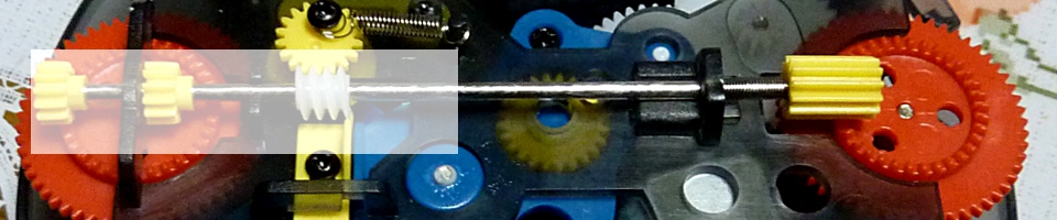
Airframe drive gear parts.

Finished drive gear subassembly.

Nose subassembly, with propeller and airframe supports and drive gear.

Dirigible assembly, with nose subassembly and drive gear fixed in place.

Dirigible with the top, bottom, left and right outer skeleton frames in place, along with the tail ladder. The strips will be inserted through slots in the ribs to make the assembly look more like a balloon.

Finished airballoon assembly. The instructions state that it’s ok to use wood glue to fasten down loose parts. And, one of the strips kept pulling out of its notch in the nose rib. Otherwise, all the strips and other pieces forcefit into place just fine. It took me 3 hours to get this far, largely because I was making beginner-level mistakes and having to disassemble part of my work and reassemble it to fix my errors. I’d started at 10 PM, and decided to quit for the night at 1 AM. (That, and I wanted to go to the store to get some wood glue.)

Starting back up the next day. A lot of these pieces require significant force to slide the tabs into the notches. That, and serious patience (especially those long, thin strips for the dirigible body). I did manage to crack one of the tail fins on the dirigible, but I was lucky in that the crack isn’t noticible unless you know where to look. Otherwise, I’m extremely surprised that I didn’t snap stuff in two with all the pushing I was doing. My fingers still hurt two days later.

Shown above, the ship front left body plate, front wheel assembly, and part of the upper deck.

There are literally a boat-load of gears for this thing, and most of them have to be assembled before doing anything further on the boat body. Above, gear assembly 1. Note that the two smaller gear pieces are not mirror-reverse images of each other. It is possible to put them on the gear shaft wrong so that the teeth are not direct aligned with each other. If this happens, flip one of the gears over and try again.

Parts for gear assembly 2.

Finished gear. This one connects to the two big paddlewheels, later.

This is my favorite part – the ratchet box assembly. Unfortunately, when the cover plate is snapped in place on the box, the ratchet (the 4-armed thing in the lower right corner) gets hidden.

Finished ratchet box, with spring pin.

Parts for gear assembly 3.

Finished gear. Notice the positioning of the spacers. This is what all those little adjustment stands are for.

Parts for the main spoke gear. This is the biggie that drives a lot of the other gears.

Finished main spoke gear, plus spacer spacing stand 4.

Parts of the rear wheel and rudder subassembly.

Finished tail.

Tail drive gear assembly parts. Note that the half-gear disks are strictly ornamental, and don’t actually turn or anything.

Finished tail drive gear subassembly.

Parts for the tail propeller.

Finished tail propellor, plus the tail drive gear and tail wheel subassemblies.

All three pieces set together in position.

Taking the above body plate, mounting the tail assembly, paddlewheel gear, and spring in place.

Now, with the ratchet box on top of the spring. This was kind of tricky, in that the notch in the end of the spring pin needed to hook into place on the spring as the box was set in place.

All of the other gear assemblies are now in place. One of the things I was surprised by for this kit is that while it includes a small tin of wax, there are no indications anywhere in the manual that any of the moving parts need to be waxed at all. I did use candle wax on the paddlewheel gear plate and the matching hole in the body plate, above, but otherwise the kit didn’t seem to need waxing, and I didn’t bother doing it to any of the other gears or surfaces.

Ship body, with the upper front and back deck subassemblies in place (see below for placement).

The ship main body, with the right body side plate snapped in place. This step took some time, because the pins and tabs of the gears and decks didn’t want to align with the side plate notches.

Other side of the current subassembly process.

Parts for the air duct thingie that ships have. Again, the half-gear piece is only for decoration.

Finished thingie subassembly.

Finished paddlewheels, and mounting support plate. I didn’t bother taking process photos for this step, because I figured I already had too many photos by now. The mounting support plate is set under the center of the paddlewheel first, then the ship is set above the wheel so that the wheel axel tabs can be put into place in the wheel. Otherwise, pushing down on the axel would damage the center of the wheel spoke piece.

Putting the dirigible on the ship main body. Note that there are only two sticks supporting the dirigible on the ship decks. This means you have to be careful while handling the airship to prevent snapping those sticks in half. Note also the white plastic ribbon. I’d glued the loose end of the one strip into its notch in the nose of the dirigible, but it was just taking too long for the glue to dry and I was bored with having to sit there holding the strip in place for an hour. So, I took the ribbon (which is used as string in Japan) and tied the strip down against the nose this way. I also took the opportunity to apply glue to all the other strip ends as well, just to make them less likely to pull free later on.

The tail wings. The two little disk pins on each wing are notched off-center, so the wing pieces look like they’re slightly downwardly curved. I think this is a nice touch.

And, we’re done. One thing I’m not as happy with regarding the instructions is that there’s nothing showing how to wind up the spring, how to hold the wheels to keep them from moving as you turn the key, or how many turns to make without damaging the spring. All the parts move freely, so that’s good. I’ve been able to turn the key 5 full rotations, and that gives me a running time of about 5 seconds, with a full distance of over 10 feet (I can’t be precise here, because my apartment is small, and the airship runs into the wall before the spring fully unwinds. I’m thinking that it might be able to cover 20 feet before stopping.) There’s a little wooden lever at the left of the back deck, but I’m not sure what it’s for. It seems to engage and disengage one of the gears, but I’ve tried sliding it back and forth while letting the airship run and I haven’t noticed it having any kind of effect on anything.

The ship took another four hours to build, so all-total I’d say this was a 7-8 hour project. If I tried it again, I might be able to bring that down to 6 hours. As I say, there wasn’t any need for the tin of wax, or the little scrap of sandpaper. There were a lot of extra parts in case something broke or got lost along the way, but I didn’t need any of them. There was also a HUGE amount of scrap wood left over – maybe 1 pound worth. But, it was fun to build, and I’m waiting for my English classes to start up so I can show it off to a few of my students.

This airship is a novelty item, and doesn’t have a lot of replay value. Just put it on a shelf and show it off to your friends at parties. Although, you can run some LEDs through the dirigible, if that’s something that appeals to you, and use it as a Christmas decoration for next year.

“Look! On the ground! It’s a dog! It’s a shoe! No, it’s super shoedog!”

ROKR Treasure Box


I received two wooden build-it kits for Christmas this year. While they’re generally referred to as puzzle kits, only the Treasure Box is a true puzzle – everything else are just build-its. Anyway, first up is the Treasure Box, by the Chinese company ROKR. (On the cover, the packaging calls it “Treature Box”, so that’s a warning as to what the English instructions inside are going to be like. But, to be honest, the instructions weren’t that bad, and the illustrations were mostly good enough to work from.) The kit is heavy, at about a pound or so, most of the weight being from the 5 sheets of high-grade 1/8″ plywood. There are 3 large sheets, and 2 half-sized sheets. There’s also a good selection of back-up pieces for anything small enough, or brittle enough, to break as you’re handling them. I didn’t realize that initially… The kit also comes with a small tin of wax, a way-too tiny piece of sandpaper, and a little bag of wooden sticks that you have to cut up for use as pins and axels.

Having read the Amazon reviews of similar kits, I knew that waxing the moving parts was critical, so I bought a box of regular candles and a cloth rag from the 100 yen shop (the Japanese version of the Dollar Store) before getting started. The first assembly is a little rotating disk tool that is supposed to be used for calculating the P-code for use in setting the combination lock. However, the manual has the full table of codes at the back, so the disk tool isn’t really necessary. It is important to note, though, that due to the way the lock is constructed, there are certain codes that don’t work. There’s a separate table at the front of the manual listing the 3-digit P-codes to not use.

Pictured above, the combination lock disk holder, pin and top lid latch subassemblies.

Assembled disk holder and top lid latch, on the box base plate. Note the little circular notch at the left of the lid latch. The kit comes with a rubber band that’s used for making the lock work. That band fits into that circular notch to pull the latch back to let the lid open up, when the correct combination has been entered.

Base assembly, with the beginnings of the front plate subassembly. The notched circle on the back side of the front plate is just there to rotate when you enter the combination for appearances. It’s not actually part of the lock itself.

Assembled lock. I really wish I’d taken a photo of the three disks before putting this part together. The disks each have a curved notch at the rim that the lid latch arm fits into when the correct combination is entered. The combination itself is set by putting little wooden pegs into slots set around the center of the disks. The lock mechanism is the standard rotating type – turning the knob makes disk 3 rotate. The peg on that disk will engage with disk 2, and continuing to rotate disk 3 will eventually cause disk 2 to engage the peg of disk 1. Turn all three disks together until the notch for disk 1 is under the latch arm. Rotating disk 3 fully the other direction engages disk 2 from the other side of the peg. Keep turning until the disk 2 notch is under the latch arm. Then turn disk 3 back the first direction until its notch is under the latch arm, and the rubber band attached to the lid and the latch arm will pull the latch into the 3 aligned notches, allowing the latch fingers to disengage from the lid, and the lid can then be opened.

The rubber band is the semi-milky white thing at the right side of the top of the lock assembly.

The front of the main box, with the combination dial. The pieces are all precision cut, and force fit together snuggly enough that you don’t need glue or nails. I made so many mistakes in putting the rubber band on the latch arm (not putting it over both latch fingers, not guiding it through the above circular notches) that in removing the faceplate and putting it back on that the snug fit was being lost.

The box has three separate mechanisms. First is the combination lock. Second is an iris door on the top of the box lid. And third is a little elevator mechanism that is used to lift whatever (tiny) treasure you put inside the elevator compartment. Pictured here is part of the elevator outer frame, and twist knobs for raising and lowering the compartment.

The outer frame and knob face are assembled to the right. We have the 2 keys for the left and right knobs, plus the assembled elevator compartment to the left.

The compartment is in place within the outer frame, in the raised position. There are two small grill doors that automatically open and close as the keys are turned. The left door is in place, and the right door and axel pin are to the right of the photos. As mentioned above, you’re supposed to wax all the moving parts so that they work against each other with less friction or binding. I decided to err on the side of caution, and I applied wax twice to all of the wheel faces, and rubbed them down with the cloth rag until the wax was slick and glossy. Most of the gear teeth were too small and close together for that, though, so I just rubbed on wax flakes, and meshed the gears together enough to get the wax to stick inside the gear teeth long enough to affix the gears in place in their assembles. After that, I worked the moving assemblies back and forth until they stopped binding against each other. Note that one of the gears for raising the compartment snapped on me as I was trying to remove it from the key axel. It was enough to take out one tooth of the gear, but not enough to affect the operation of the gears themselves. At this point, I hadn’t figured out that I had a spare for that piece, so I just left it as-is. If I had known, I might not have done anything differently, because I’d have needed to completely shatter the bad piece to get it off the axel to replace it. No harm, no foul.

The finished elevator compartment subassembly, plus the two keys. It’s a pretty neat little design, and the gears in the center of the front plate intermesh so that turning just one key will cause the top doors to open up and the elevator compartment to rise smoothly. But, using both keys together looks more cool.

The elevator subassembly has been put into place on the base plate along with the combination lock assembly. The back faceplate subassembly is to the left of the photo, waiting to be placed on the base. I really like the way the cuts have been made to allow the plywood to be curved into shape without breaking or requiring excessive molding.

The finished main box assembly, back side. The two fingers at the top front of the photo are the hinges for the lid.

And the front side.

Now, with the lid base piece attached.

With the lid down, and the combination lock fingers holding it closed. Note that central circular fence piece. That started out as a flat ribbon, and you’re supposed to fit the two ends into each other to make the ring. That thing literally self-destructed in my hands. Fortunately, this is when I discovered that the kit included spare parts, and that included having a second fence. I was a LOT more gentle with the backup piece, and managed to fit it into the lid slots without any more drama.

All that’s left now is to make the top lid iris cover. Lots of cutting little pins here, and shaving them flat with the surfaces of the plates. Each of the two assemblies consists of 2 parts each, to create a kind of “insert plate” and a “two-tiered holder tray.” The five wing shapes will make up the iris door inside the insert plate.

The finished iris door assembly, partly opened. The outer top disk rotates to open and close the iris. Looking at this now, I should have been a little more thorough in shaving those pins down flat with the top plate. Oh well. If anyone I show this to complains, maybe I’ll try fixing it in post.

The finished iris door assembly, the elevator compartment keys, and the main box. Almost done.

As I said above, this thing is precision cut, and maybe a bit too precise. Most of the holes for the wooden dowel pins were too tight for the pins to be inserted easily, so I ended up boring them a bit wider with a small phillips head screwdriver. As for the irs door assembly, the notches and fingers didn’t want to align right away. I used my cutter knife to shave a little bit of wood along all the notches. I was careful to not take off too much at any one notch, but when I finished, the lid cover slide into place just a little too smoothly. I might talk myself into using some wood glue to hold the lid in place better. Still it looks really nice.

Back side with the keys in place. It looks better without the keys, so when it’s displayed on a shelf, I set the keys off to the side a ways.

The iris door doesn’t lock shut, but it can’t be used to get to the main inner compartment, either. You can use the little cup here inside the iris to hold a ring or a couple coins.

The markings on the combination dial are off a half turn on all three notch dials. Instead of 4-6-4, which is what the pins are set to, the box unlocks at 3.5-5.5-3.5. Otherwise, no problems. It took me 7-8 hours to finish this kit, and a lot of that time was spent waxing surfaces and cutting little dowel pins. It’s a fun little kit to make, and it’s a good way to teach kids how combination locks and iris doors work, and how to gain physical assembly skills.

But, if you’re looking for a lock box for protecting anything of significant size, this kit isn’t it. It’s a novelty, it’s not supposed to be practical. The dimensions are: 10 cm wide (4″), 14 cm front to back, including the key lengths (5.5″) and 9 cm tall (3.5″). The compartment is 3.5 x 3.5 x 4 cm (1.4″ x 1.4″ x 1.6″).