
(I don’t have any photos of my own to include here this time, because my camera got dropped and it hasn’t been repaired yet.)
Gakken’s latest kit, number 37, (2950 yen) is the Animaris Imperio, AKA -The Bipedal Robot. This is the third in the series of machines based on Theo Jansen’s linkage design. (According to an earlier Gakken newsletter, “Imperio” was chosen by Jansen for the beest’s name because it refers to the Emperor Penguin in Latin, and was influenced by the beest’s “waddle walk”). The idea here is to use a pair of control rod assemblies (one pair per leg) that causes the leg to pivot at the ankle to maintain the beest’s center of balance throughout the walk cycle. The exact details of this process are described in one of the articles in the mook. The beest’s primary motive power, as with the previous 2 kits, is a wind-driven fan. (Note that the cover image on the mook is inaccurate; the pivot action at the ankle causes the beest to tilt significantly towards the side of the planted foot. The picture has it more vertical in midstep.)
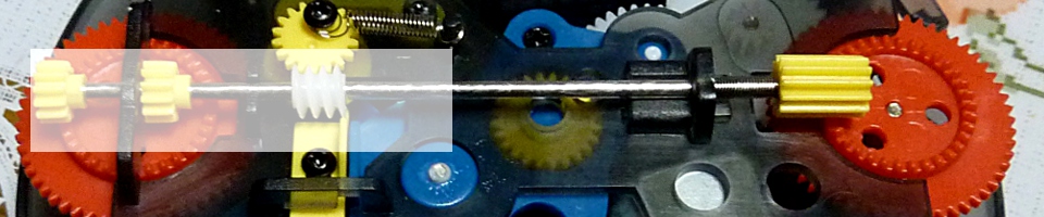
There’s no new theory to talk about this time. The crankshaft has 4 crankpins, two for each leg (the 2 crankpins work together to push or pull the left and right sides of the foot to create the pivot motion at the ankle). The fan attaches to a preassembled driveshaft built into one of the frame pieces, which in turn spins the gears on the left side of the beest to rotate the crankshaft. One interesting thing is that the design includes a long plastic tube within the frame, containing 4 steel balls that roll over the supporting foot for balance (called the “balance bar”). Mods suggested in the mook are to add a marble machine to the top of the frame, to turn the beest into a baseball field mascot pulling a roller drum, to place an LED with a small battery inside the balance bar, and to add a micro-motor and lithium battery.
(Gakken’s official youtube video.)
Suggested assembly time is 60 minutes, and it took me 90, mainly because I had lots of problems understanding the pictures and I had to take the legs apart several times to fix my mistakes. In essence, though, the idea is simple. You start out with the A-frame for the left leg, and start attaching the triangle pieces to each side of the A-frame, while putting a long or short control rod on the pins in the middle of the leg. A pair of straight pieces are used to form a box with the second set of triangles. When you’re done, you’ll have something that looks like a crane arm, with one end of the “crane” connected to one pin of the A-frame. Most of the connections are just slotted pin-and-holes, but you’ll need to use the small metal screws to fasten the pieces together securely (being careful to not strip the threads). One tricky part is when you have to pull the left and right halves of the leg apart to get one of the longer pins to fit in the hole. The plastic is flexible, but you want to avoid pulling so hard as to snap something. Repeat with the right leg.
When both legs are completed, you assemble them along with 3 more A-frame pieces (middle with the drive shaft, plus left and right ends (the gear shaft is on the left when the kit is facing you)). Together, the 5 A-frames make up the “body frame” of the beest. Put the small hex nuts into the plastic end knobs, run the stiffener rods through the holes at the three corners of the A-frames, and tighten. For the “central” rod (the one not at the top or bottom of the legs), you’ll need to also put on the balancer holders – two short arms that will hold the plastic tube with the steel balls inside. The key things to be aware of here are that the A-frame pieces need to be aligned so that they all have the crankshaft holder arms lined up in the same direction. And second, that the balancer holders point towards the back of the machine within the gap in the legs. Attach the long and short control rods as shown in the diagram. Hand turn the crankshaft to make sure it rotates easily. If not, at least one of the control rods is probably in wrong and will need to be fixed.
If the legs move freely, then add the balancer (put the balls into the tube, put the threaded endcaps on the tube, and put the assembly into the holders). Stick the two little squares of sponge into the bottoms of the feet so they’re at the inside back corners where the unattached parts of the leg will press down on them. Attach the feet to the legs as shown in the diagrams. Finally, put on the gears, assemble the fan using the double-sided tape, and put the fan on the fan shaft.
Regarding tools, you’ll need a small Phillips head screwdriver, and you may want a sharp pocket knife. The leg pieces need to be removed from the “tree”, and you might want to shave the flash from the parts afterward.
The mook isn’t particularly remarkable this time, unless you like Gundam. The first article is an interview with Kunio Okawara, mecha designer for the Gundam robots. This is followed by another piece on Theo Jansen, plus explanations of the Imperio’s linkage system and comparisons with the structure of the human leg. There’s an overview of other bipedal robots (including the Asimo of course), and then the suggested mods for the kit. Hobbyist articles include one on a group of people making a 2-wheeled rocket-launched robot, and 2 guys making their own scaled-version of a giant mecha. For the first article, the idea is to launch a rocket containing the robot and eject it near the goal site. Then, the robot rolls over to reach the goal on its own. A third hobby article describes a guy that makes small walking robots out of foamcore.
There’s a long section on the theory of how animals and people walk, additionally contrasting humans with penguins.The mook ends with another of Yoshitoo Asari’s Science Manga, this one entitled “What Shape is a Robot?” This time, our heroes are approached by a stranger wearing a hood, with just its glowing eyes visible. It’s a robot and has no body, so it asks them what the ideal shape should be for it. The kids take turns trying to argue for humanoid, cart-shaped, or factory-specialized arms. Examples of different applications are the Mars rovers and the Hayabusa explorer. Finally, they realize that there is no one good shape, that everything is determined by need, application and environment, and the stranger leaves, happily.
As with most Otona no Kagaku kits, the main point to buying it is to make the thing. There is limited replay value unless you modify it significantly. The mook is less visually interesting this time, and it really helps if you can read Japanese for the articles, or if you really like Gundam. Fortunately, it is somewhat cheaper than the other beests (2950 yen is roughly $36 USD without the import markup), but it is a smaller kit, measuring about 4″ x 4″ x 6″. Recommended if you are a fan of Jansen’s beests, or if you teach mechanical design.

Next up – Kit #38, the Radio Wave Flap Clock. No price given, tentatively scheduled for a Spring, 2013 release.


